More...

More...
|
| © 1996 Michael J. Hammel |
 |
Review: The AC3D Modeller
There are only a few 3D modellers available for Linux: AMAPI (which may
now only be available for the Mac, based on one report I've received),
Midnight Modeller, SCED/SCEDA, and AC3D. Each of these has its advantages
and disadvantages. I've tried each of these at least briefly. A couple,
SCED and AC3D, I've used to actually create scenes. Lets take a quick look
at one of these - AC3D.
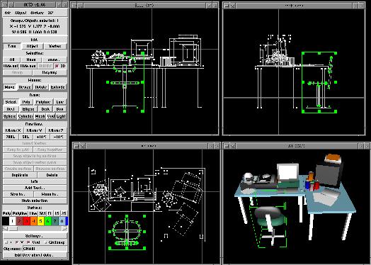
| AC3D comes from Andy Colebourne. It is a shareware modeller that comes in binary format only. It is available for Linux, SGI's and Sun's (both SunOS and Solaris). Once registered you have access to a private Web site from which you can download the full version of the software. Documentation is a bit sparse (a common problem with much of the software available for Linux, in this authors opinion), consisting of about 12 or 13 pages formatted in either HTML or Postscript. The distribution package contains the binary, the HTML manual with a few images and a set of object files that are necessary for packages which use the Mesa Graphics Library, which AC3D does. |
|
| One of the nicest features is the ability to extrude a 2D shape into 3 dimensions. Lets follow an example of this. First, select the "ellipse" drawing function from the control panel and create a stretched out ellipse in the XY orthographic view. |
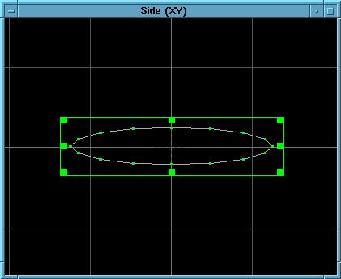
Figure 2: An ellipse |
| Next, change the Edit type to "vertex" in the control panel and select all the vertices on the lower half of the ellipse (but not the ones on the end of the ellipse). Delete these with the "delete" function in the control panel. Then select the two lowest vertices and insert some new vertices (as shown in Figure 3). |
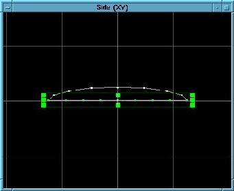
Figure 3: The ellipse has been halved and some new vertices added. |
| This next part is a little tricky. What you want to do is select the vertices on each end of the object and move them, one at a time, until you get a slightly rounded effect. Then select 4 or 5 of the vertices on the back end (the left side in Figure 4) and strecth them out a little, to flatten the wings trailing edge. Then get rid of the extra vertices along the bottom of the wings edge by selecting them and using the "delete" function in the control panel. The result should look something like Figure 4. |
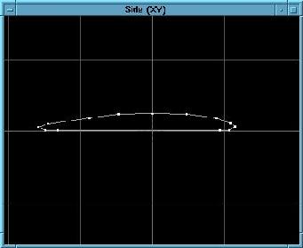
Figure 4: The wing edge takes shape |
| This isn't bad, but a wing should be smoother around the top and edges, so change the Edit type to "Object" and select the wing. Then use the "Spline Surfaces" option from the Object pull-down menu. This adds a bunch of new vertices to the object and creates a smoother line around the wing. |
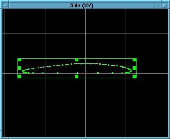
Figure 5: Smoothing the wing edge. |
| Now lets take this simple shape and extrude it. Make sure the Edit type is still "Object" and select the wing edge. We need to change to the XZ orthographic view window. Up to this point we've been using the XY viewport. Click on "Extrude" under the Mouse options in the control panel. Grab the object in the XZ viewport and drag up. The original points stay put and a new set of points is moved to where ever you drag to. Once you let go of the mouse button you'll see the new points get connected to their corresponding points on the original object. Notice how the connecting lines aren't quite straight. This would be bad for a real wing, so we'll straighten them out. |
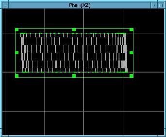
Figure 6: The wing edge gets extruded. |
| In this next figure, the control panel was used to change the Edit mode to "vertices" and the vertices on the new side of the extruded object have been selected. Once selected, the "move" option under the Mouse features allows the selected vertices to be moved as a group. When these vertices are moved the lines connecting them to the opposite end are redrawn. You can play with this a bit in order to get the connecting lines to become straight. Note that its not absolutely necessary to correctly align the two ends of the extruded object, but this is one way to do so if you feel it necessary. |
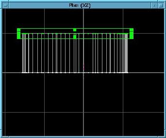
Figure 7: The ends of the extruded object are aligned. |
| Now switch back to the "object" Edit mode and select the object. The bounding box (in green) has handles that can be grabbed to drag the bounding box to resize the object. Use the middle top and bottom handles to make the object wider in the XZ view. |
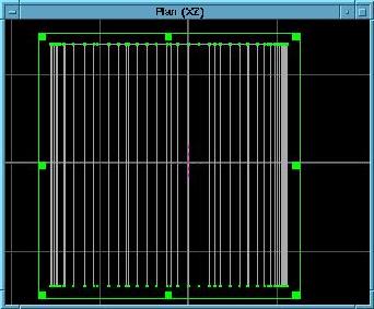
Figure 8: Stretch the object a bit. |
|
Next, switch back to "vertices" Edit mode and select the vertices
on one end of the object. Click on "Create Surface" under
Functions in the control panel. If the surface (as viewed in the 3D
view) does not appear solid you can select "Poly" under Surface to
create a solid surface to close the end of the object. Repeat this process
for the other end.
Viola! You've got a solid surfaced wing, just like the one in Figure 9. (The grid is an option for the 3D view window and not part of the image.) Of course, this is a pretty simplistic example, but you should get the idea of how easy it is to create shapes using AC3D. You'll need to export the file to POV or RIB format and add some real textures to finish up the project, of course. |
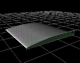
Figure 9: The solid surfaced wing. |
|
|
more IRTC...
The contest started in earnest in May/June of 1996. The topic then was
Time and there were some stunning entries. In July/August we had fewer
entries, but the topic - Summer - was a little tougher to nail down.
In September/October we hit the jackpot with Science Fiction. Well over
200 entries were submitted for this round. Thats quite a difference from
the 20-30 submitted during Matt's original contests. Fortunately much of
the work for viewing, voting, and tabulating information has been
automated. The contest has been great fun and has been accompanied with
lively discussions on the associated irtc-l mailing list.
Unfortunately, there are always those that have to try to ruin things
for everyone else. We had some people submit images that were fair but not
likely winners. They then submitted multiple votes. A vote consists of
ratings of all the images with values between 1-20 for each in 3
categories - needless to say
this takes awhile to accomplish. Any vote that does not include ratings
for all images is not counted in the final tally. The multiple votes were
done offline (which is permissable) and submitted from different email
accounts. The artists images received very high marks while all the rest
received very low (within a very small range) ratings. Then they got some
of their friends to do the same thing. Beyond this, others have
submitted numerous entries that they had made in the past (prior to
the contest) that just happen to fit the category (how many 3D artists, for
fun or profit, have *never* made a space scene?) in order to turn the
contest into their own private gallery. The spirit of the competition is
lost on some people, I'm afraid.
I haven't done any of the automation nor have I worked on the very
nice web site for the contest. But I've watched Chip and Bill do so.
Its very frustrating knowing how much effort they put into this,
trying very hard not to give themselves or anyone else unfair advantages
and still make the contest fun for everyone only to see someone still try
to cheat the system. Why? For a couple of CDs? Remember when the
Internet was a friendly, honest place?
Still, the contest continues and the Admin Team is working on ways
of keeping the contest fun, open to participation, and fair. The
guys could use a new host for their contest. Walnut Creek, the current
host, appears to be limiting ftp connections and the amount of disk space
required for 200+ images can get rather large.
If you are into 3D rendering for the fun of it you owe it to yourself
to take a shot at the IRTC. Its fun to see how your images stack
up against others. Many of the voters offer comments on the images which
can very useful in any future images you render. Check our the
IRTC Web Site
to get more details and join in!
|
|
| © 1996 by Michael J. Hammel |